 | ||||
HOME | ESR Meters | LCR Meters | Continuity-Low Ohm Meter |Geiger Counters | Tektronix | Metal Detectors | Contact Projects | Other Lab Tools | Solar | Master-Slave Switch | Semiconductor | ||||
 | ||
 | |


General-purpose ESR meters do not have to be precise; we are looking for gross changes from normal (in the region of 50%). Either of the designs mentioned will be usable although both will drift a bit with temperature.
Bob Parker’s meter is an elegant design for those who like a digital readout. (Because of the pulsed nature of the test current, a standard A-D converter would need to be preceded by a sample and hold circuit adding to the complexity.)
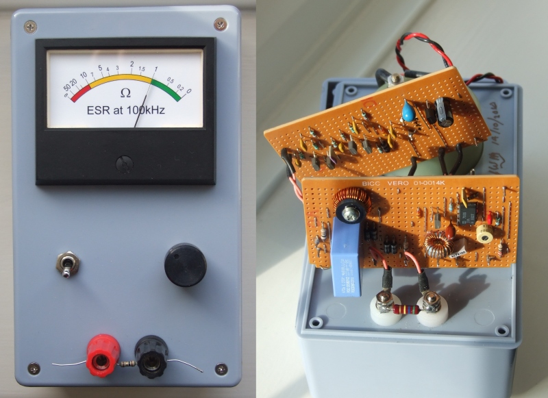
My own preference is for an analogue meter and below are some notes on a design I posted on another forum a while back. I did not write this up as a project for others to build, more to show the design considerations involved.
My requirements were: Indication from 0.2 to 20 ohm Measurement frequency 100kHz Protection against charged capacitors and 240vAC Temperature stability Power from 9v PP3 with low current consumption
A quick look at typical ohmmeter circuits showed that to achieve a scale 0.2 to 20 ohm, a source resistance (Rs) of around 2 ohm would be required. The modified form of Option1 was chosen as the easiest to implement. As a starting point Rs’ and Rm were chosen as 1 ohm.
To avoid excessive drive power a sensitive detector would be required. Experimenting with a millivoltmeter showed that with 1 ohm across its input, a FSD as low as 1mV rms was practical. This meant that the drive current required would be 2mA rms (with Rx = 0 Rs’ and Rm are in parallel).
In my opinion OP-AMPs are not the best choice at 100kHz; the gain of most general-purpose types is low at this frequency (< 30). As DC precision is not required a single transistor can easily out perform them. To drive a diode bridge from 1mV you need a gain of at least 1000 (in round terms) implying a gain-bandwidth product 100MHz minimum, no the province of a common Op-Amp. For good linearity down to 1/10 FSD this figure goes up to 1GHz! (As an aside, I think this is how several of the other ESR meters 'get away' with Rs in the order of 20 ohm. Low gain before the diodes gives an expanded scale at the expense of temperature stability.)
A 5v power rail was chosen using a low drop-out regulator which willregulate down to 5.2v input with a quiescent current of < 200uA. The detector circuit was based on a design first seen in ‘Ferranti E-Line Transistor Applications’ 1970. (see 2nd image). T1 & 2 drive a 100uA meter to FSD with 22mVrms on the base of T1. T3 & T4 form a pre-amp with a gain of around 22 to give the required 1mV sensitivity. (The LF gain is approx 28 (=R9/R8 + 1) with an HF roll-off provided by C7) Capacitor values were chosen for 100kHz operation (100nF at 100kHz has a reactance of 16 ohm) The circuit was built and found to perform as expected. Deflection for zero input with a 1 ohm resistor across the input was around 0.5%FSD.
Surprisingly no supply decoupling other than C8 (tantalum) was required for stability. Current consumption was under 2mA.
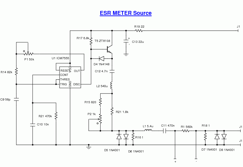
The source was based on a CMOS version of the ubiquitous ‘555, swapping the normal roles of the output and discharge pins gave a 1:1 Mark-Space ratio and increased drive current at the expense of an active pull-up (T5) (3rd image) (R21, a SOT resistor, was added later to trim the M-S ratio to exactly 1:1)
I used the CMOS version of the '555 (http://www.intersil.com/data/fn/fn2867.pdf) Much lower power and no nasty current spikes on the supply rail, but the output starts to sag sourcing more than about 1mA from a 5v supply. The (open drain) discharge output can easily sink 15mA and an external active pull-up ensures a large enough source current. Driving the timing resistor from the output of a standard (bipolar) '555 doesn't work as well, the output 'High' voltage is only about 3.5v which is only just above the 2/3Vcc upper threshold of the comparator section. This will give a very asymmetric M:S ratio. see (http://www.unitechelectronics.com/NE...#internal-ccts).
An inductor L2, originally a 1mH unshielded inductor, was added to attenuate the harmonic content of the square wave. This had such a large stray field that probing with a ‘scope was difficult. It was replaced by a toroidal inductor, which cured the problem. The DC block (C12) was chosen to resonate with this inductor. The pot network was chosen to give an adjustment range of around –20 +40% to allow for the effect of test leads. Protection against charged capacitors was provided by C11 an X2 rated capacitor. Its reactance was cancelled by L1 another toroidal inductor.
Without L1 the reactance of C11 (3.5 ohm) would raise the source impedance 4 ohm. This would mean that mid scale would be around 5 ohm and, for example, that the current for an ESR of 0.2 ohm would be 2.6% below FSD rather than 9.1% below FSD. (All assuming that the reactance ot the test capacitor is negligible.) The loss associated with C11 & L1 added less than 0.2 ohm to the effective value of Rs. With a loaded Q of less than 2 (Xc = 3.5, Rs = 2) minor frequency drift should not cause problems. As a bonus the reactance of C11 at 50Hz is 6.8k so any mains pick-up will be attenuated by 76dB. Protection was completed by D5 to D8. (I had a senior moment here, a single pair of back- to-back diodes between R16 and R18 would have been better.)
Finally there was the problem of re-scaling the meter. First I measured the meter reading for a range of known resistors. Then I removed the scale plate and scanned it (with steel rules as a reference). By importing the scan into TurboCAD I was able to accurately measure the dimensions (both linear and angular). After a steep learning curve I found that it was fairly easy to draw the new scale and even tilt the numbers to match.
Current consumption for the completed unit was 3.7mA.
A perfect 1uF capacitor should give an apparent ESR of 0.56 ohm with Rs = 2 ohm. I measured a film 1uF capacitor and got a reading just below 0.5 ohm. The slight discrepancy is caused by losses in L1 / C11 raising Rs to around 2.2 ohm.
Jim
ps just noticed a mistake in my original post, T4 is a ZTX502 (not 302)If the high voltage protection is omitted, the source may be simplified and no inductors are required.
What so special about this one is its using very-very low test voltage at 100Khz, under simulation I've done at ltspice it shows the test voltage across the cap is under 5 mV pp and find it very interesting and works great at the simulation of course. Also the test signal is almost in pure sine wave instead of common used square signal.